A1351
High Precision Linear Hall Effect Sensor IC
with a Push/Pull, Pulse Width Modulated Output
17
Allegro MicroSystems, Inc.
115 Northeast Cutoff
Worcester, Massachusetts 01615-0036 U.S.A.
1.508.853.5000; www.allegromicro.com
(Decimal Equivalent)
Code 5
Bit Field Selection
Address Code Format
Code in Binary
Fuse Blowing
Target Bits
Fuse Blowing
Address Code Format
(Binary)
1 0 1
Bit 2
Bit 0
Code 4 Code 1
(Decimal Equivalents)
Figure 3. Example of code 5 broken into its binary components,
equaling code 4 and code 1.
Locking the Device
After the desired code for each parameter is programmed, the
device can be locked to prevent further programming of any
parameters. See the Lock Mode section for lock pulse sequence.
Additional Guidelines
The additional guidelines in this section should be followed to
ensure the proper behavior of these devices:
" A 0.1 糉 blowing capacitor, C
BLOW
, must be mounted between
the PWMOUT pin and the GND pin during programming, to
ensure enough current is available to blow fuses.
" The final application capacitance, C
L
, should be used when
measuring the output duty cycle during programming. (The
maximum load capacitance is 14.7 nF for proper operation.)
" The blowing capacitor, C
BLOW
, should be removed during
measurements; it should only be applied when addressing bit
fields and when blowing fuses.
" The power supply used for programming must be capable of
delivering at least 26 V and 300 mA.
" Be careful to observe the t
LOW
delay time before powering
down the device after blowing each bit.
" The following programming order is recommended:
1. PWM carrier frequency
2. Coarse D
(Q)
3. Sens
4. D
(Q)
5. LOCK (only after all other parameters have been
programmed and validated, because this prevents any further
programming of the device)
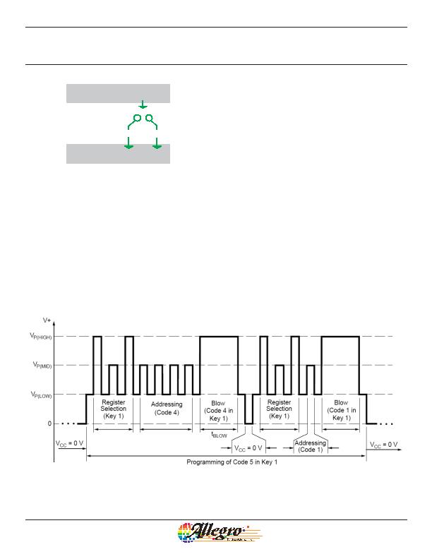
Figure 4. Example of programming pulses applied to the PWMOUT pin that result in permanent parameter settings. In this example, the register
corresponding to key 1 is selected (twice) and code 5 is addressed and blown (in two stages).
发布紧急采购,3分钟左右您将得到回复。
相关PDF资料
A1354KKT-T
IC SENSOR HALL EFFECT 4-SIP
A1356LKB-T
IC SENSOR HALL EFFECT 3 SIP
A1361LKTTN-T
IC HALL EFFECT SENSOR LN 4-SIP
A1374EKB-T
IC SENSOR HALL EFFECT PREC 3-SIP
A1422LK
IC SENSOR HALL EFFECT AC 4-SIP
A1425LK
IC SENSOR HALL EFFECT AC 4-SIP
A1645LK-I2
IC SENSOR HALL EFFECT AC 4-SIP
A3230LUA-T
IC SW HALL EFFECT CHOPPER 3-SIP
相关代理商/技术参数
A1352-035
制造商:AVX Corporation 功能描述:
A1352-037
制造商:AVX Corporation 功能描述:
A13532-43N
制造商:Harris Corporation 功能描述:
A1354
制造商:ALLEGRO 制造商全称:Allegro MicroSystems 功能描述:High Precision 2-Wire Linear Hall Effect Sensor IC with Pulse Width Modulated Output
A13546-000
制造商:TE Connectivity 功能描述:VARISTOR 680V 20MM RADIAL 制造商:TE Connectivity 功能描述:VARISTOR 680V 10KA DISC 20MM 制造商:TE CONNECTIVITY RAYCHEM-POLYSWITCH 功能描述:Var MOV 420VAC 560VDC 10000A 680V Thru-Hole Bulk
A1354KKT-T
功能描述:IC SENSOR HALL EFFECT 4-SIP RoHS:是 类别:传感器,转换器 >> 磁性 - 霍尔效应,数字式开关,线性,罗盘 (IC) 系列:- 标准包装:1 系列:- 传感范围:20mT ~ 80mT 类型:旋转 电源电压:4.5 V ~ 5.5 V 电流 - 电源:15mA 电流 - 输出(最大):- 输出类型:数字式,PWM,8.5 位串行 特点:可编程 工作温度:-40°C ~ 150°C 封装/外壳:20-SSOP(0.209",5.30mm 宽) 供应商设备封装:20-SSOP 包装:Digi-Reel® 其它名称:AS5132-HSST-500DKR
A1354KKTTN-T
功能描述:IC HALL EFFECT SENSOR 2WIRE 4SIP RoHS:是 类别:传感器,转换器 >> 磁性 - 霍尔效应,数字式开关,线性,罗盘 (IC) 系列:- 标准包装:1 系列:- 传感范围:20mT ~ 80mT 类型:旋转 电源电压:4.5 V ~ 5.5 V 电流 - 电源:15mA 电流 - 输出(最大):- 输出类型:数字式,PWM,8.5 位串行 特点:可编程 工作温度:-40°C ~ 150°C 封装/外壳:20-SSOP(0.209",5.30mm 宽) 供应商设备封装:20-SSOP 包装:Digi-Reel® 其它名称:AS5132-HSST-500DKR
A1354P1-2
制造商:APEM 功能描述: